|
|
|
Who's Online
There currently are 6043 guests online. |
|
Categories
|
|
Information
|
|
Featured Product
|
|
|
 |
|
|
There are currently no product reviews.
 ;
El producto satisface las necesidades del servicio t
;
This is a good quality scan of the Operation & Maintenance (Service) Manual for the PAL version of this high-band broadcast umatic, BVU-800P
All schematics and lineup procedures appear to be included in this one manual AFAICT.
The file size is just over 113 MB which gives an idea of the quality and number of pages.
All of the schematics, which contain some fairly small print, are easily readable when you zoom into the page.
John Thompson, Newcastle Upon Tyne, England.
;
Good quality, all schematics of few of models. There is also short form of user manual and regulation manual.
;
Perfect copy of the service manual. you can enlarge every page, and it comes up
with all details.
;
It´s very very nice manual with all, what i need. Original in good quality. Very fast business. Very much thanks...
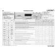
TKR-850
INSTALLATION
3. External Speaker (KES-4)
The TKR-850 has a internal built-in speaker (5W/8�), and the external speaker output from the TEST/SPKR connector (15-pin) on the rear of the radio is 4W/4�. Use external speaker KES-4.
3-1. Connection for the KES-4 With the TKR-850 s When taking the AF output from the TEST/ SPKR connector (15-pin) on the rear of the radio
The following tools are required for changing the connector.
Fig. 4-1
� Extracting tool
The following extracting tool is recommended : Molex Inc. Order No. : 11-03-0002 1. Remove the connector with jumper from the external speaker connector on the rear panel of the radio. (Fig. 41) Note : Save the jumper, which is required when the radio is used without the external speaker. 2. Remove the terminals with the jumper from the connector housing holes number 9 and 12 using the extracting tool.
Removing the jumper lead (Fig. 4-2)
1) Insert the extracting tool (11-03-0002) into the connector while pushing the jumper lead in the direction of (a). 2) Push the extracting tool into collapse the barbs of the crimp terminal. 3) Pull out the lead while continuing to push the extracting tool in the direction (b). 3. Reinsert the terminal with the black and white stripe lead into hole number 12, and the terminal with the black lead into hole number 6. (Fig. 4-3) 4. Attach the connector to the external speaker connector on the radio.
Fig. 4-2
Note :
Relationship between TEST/SPKR connector (15-pin) connection and speaker output. When pins 9 and 12 are shorted : Built-in internal speaker is used. When pins 9 and 12 are open and output is from pins 6 and 12 : KES-4 is used.
Fig. 4-3
14
|
|
|
> |
|