|
|
|
Who's Online
There currently are 5743 guests online. |
|
Categories
|
|
Information
|
|
Featured Product
|
|
|
 |
|
|
There are currently no product reviews.
 ;
I am very happy regarding the online purchase of this manual from Owner-Manuals.com as with this I could set right my Denon CD player and Amplifier.
I once again sincerely thank them for the prompt service which was rendered to me.
N. Shanker
;
More than pleased with my prurchase, very good product for the price.
;
Manual-link came 30 minutes after having paid for an extremely rare (40 years old) item (sony icr-120) and helped me to get the radio rework again. So really good help for me, fast and reliable delivery and -taken that into consideration- a very reasonable price for that service. So thanks again! Mike, Germany
 ;
Some of the pictures in this manual are a bit irritating. I had to dissassemble the unit and some of the screws have different threads, which is not mentioned in this manual. Also some of the drawings of the boards look different than the actual boards.
After all, the manual was very useful. I was able to recalibrate the capstan drive and it is working fine again.
;
This manual is very good. 303 pages scanned in a very high resolution. My camera has bad, leaking capacitors which all of the V5000 models are suffering from these days.
There is a huge part list with all capacitors, transistors etc. in this manual which helped me a lot. Otherwise I would not have been able to buy replacement parts.
The dissassembly guide is very enormous and detailed. Unlike on the Panasonic MS1 manual I downloaded here it actually looks like the real parts look. And the screws are labeled correctly, so you shouldn't have any left after the repair. ;)
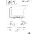
LZ-651W
ADJUSTMENT
No. Adjustment item Measurement point Adjustment part 6 CONTRAST TP204 (G OUT) TEST mode CH13 the white to the negative white is 2.7V ± 0.1V Adjust the amplitude value so that the waveform between 7 Y GAIN TP204 (G OUT) TEST mode CH2 the pedestal to the 10 step signal is 3.1V ± 0.1V Adjust the amplitude value so that the waveform between 8 GAMMA1 TP204 (G OUT) TEST mode CH11 the pedestal to the 3 step signal is 1.4V ± 0.1V Adjust the amplitude value so that the waveform between 9 GAMMA2 TP204 (G OUT) TEST mode CH12 the pedestal to the 10 step signal is 3.2V ± 0.1V Adjust the amplitude value so that the waveform between 10 R SUB BRIGHT TP203 (R OUT) TEST mode CH8 the 1 step signal to the negative 1 step signal is 3.3V ± 0.1V Adjust the amplitude value so that the waveform between 11 B SUB BRIGHT TP205 (B OUT) TEST mode CH9 the 1 step signal to the negative 1 step signal is 3.3V ± 0.1V R SUB 12 CONTRAST B SUB 13 CONTRAST 14 VCOM CN501 16PIN (TP611) TEST mode CH1 7.4V ± 0.1V It adjusts so that the flicker level will be the minimum 15 FLICKER DISPLAY TEST mode CH23 (Auto dimmer off / Bright = max / Zoom mode) The screen of NAVI is made into 2 screen mode. It PICTURE 16 POSITION end of a screen. INPUT VIDEO SIGNAL : 10STEP VIDEO SIGNAL (NTSC 1.0Vp-p) DISPLAY VR501 adjusts so that an active window may come to the right TP205 (B OUT) TEST mode CH15 the white to the negative white is 2.5V ± 0.1V Adjust the amplitude value so that VCOM square wave is Oscilloscope TP203 (R OUT) TEST mode CH14 the white to the negative white is 2.9V ± 0.1V Adjust the amplitude value so that the waveform between Oscilloscope Adjust the amplitude value so that the waveform between Oscilloscope Oscilloscope Oscilloscope Oscilloscope Oscilloscope Oscilloscope Adjustment value Adjust the amplitude value so that the waveform between Oscilloscope Measuring instrument
The definition of video signal and pedestal signal
negative pedestal
negative 1 step
white
negative white 1 step pedestal
9
|
|
|
> |
|