|
|
|
Who's Online
There currently are 5960 guests online. |
|
Categories
|
|
Information
|
|
Featured Product
|
|
|
 |
|
|
There are currently no product reviews.
 ;
It`s not your fault tear down is rather incomplete. It doesn`t have complete instructions as to deconstruction for repair.
 ;
THANK YOU FOR A GOOD TRANSACTION, NICE COPY, CLEAR
;
Very Good! All the diagram are easy to read, and its complete.
;
This was an excellent source of detailed assembly information on a device which is at least 12 years old. A very lucky find, coupled with great service.
;
Excellent Service Manual and best price on the Internet. This Service Manual covers everything you could ever need including full circuit schematics, component layout diagrams, stripdown procedure and full parts list/breakdown. I needed this to carry out a modification to one of these headunits and this manual covered everything I needed. Fast delivery, processed within a few hours.
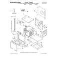
KRF-V7070D/V8070D/X9070D/VR-7060/7070/7080
EXTERNAL VIEW / ADJUSTMENT
EXTERNAL VIEW
Knob (K29-8107-02) Panel * (A60-) Knob ass'y * (K29-) Front glass * (B10-) Knob ass'y * (K29-) Knob * (K29-)
VOLUME CONTROL POWER
STANDBY
THX SPEAKER EQ
ON/STANDBY
DOLBY DIGITAL DTS CS II DSP STEREO INPUT MODE DIMMER
ACTIVE EQ THX
A SPEAKERS B
SPEAKER EQ ACTIVE EQ
DOWN MUTE DVD/6CH CD/DVD PHONO TUNER SOUND TONE
PHONES
UP
MULTI CONTROL SETUP
LISTEN MODE AV AUX S VIDEO VIDEO L-AUDIO-R
VIDEO 1
VIDEO 2
VIDEO 3
MD/TAPE BAND AUTO MEMORY
Phone jack (E11-0271-05)
Knob (K29-8111-02)
Knob * (K29-)
Pin jack (E63-1251-05) Cylindrical receptacle (E56-0033-05)
Illust. is VR-7060. * Refer to parts list on page 29 .
ADJUSTMENT
No. ITEM INPUT OUTPUT SETTINGS SETTINGS SPEAKER : A CN11, FL ch. CN10, FR ch. CN14, SL ch. CN13, SR ch. CN12, C ch. CN15, SW ch. X09(A/5) RECEIVER SETTINGS ALIGNMENT POINTS VR1(FL) VR2(FR) VR3(SL) VR4(SR) VR5(CENTER) VR6(SUB WOOFER) X09(A/5) ALIGN FOR FIG.
AUDIO SECTION
<1>
IDLE CURRENT
-
(FRONT 2ch MODE) Volume: Minimum
Adjust every potentiometer 10 minutes later after turned the power on.
Idling Current Adjustment All power amplifier stage need idling current adjustment after the installation of TRAIT transistor. 1. Connect a voltmeter to CN11 with the correct polarity as indicated by the PCB silk print. 2. Adjust the preset, VR1 to get 8.8mV (Idling current = 20mA) at the voltmeter reading. 3. Repeat step 1 and 2 for all other channels.
3
|
|
|
> |
|