|
|
|
Who's Online
There currently are 6043 guests online. |
|
Categories
|
|
Information
|
|
Featured Product
|
|
|
 |
|
|
There are currently no product reviews.
 ;
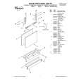
The AKAI 1720 model reel to reel tape recorder described in this Manual is quite an old unit - circa late 1960's. As a consequence, the description of the mechanical details - and adjustments thereof - is quite critical. The manual does this quite well. The schematics are also well presented and have detailed PCB overlays. Probably the only negative is that some half-tone detail has been lost from the original manual as it has been scanned in simple B&W.
 ;
Perfect source for service manuals: fast and professional transaction; high quality, perfect readable and largely scaleable PDF; complete schemes, diagrams and spare part list. Tnx a lot, cu again!!!!
;
I got your link from a friend and I must say that I am really satisfied with your service. Specially this B&O manual I didn't find anywhere on the web... but you could deliver it :-) . You deliver very fast and the copy is of good quality. So your webpage is bookmarked. Thanks
;
This was the Sony CCU-500A Service manual I was looking for.
The price was reasonable.
The permission to download was quck.
I will use Owner-Manual.com for all my manual needs.
;
Excellent printing quality.
A complete and very usefull service manual with all details.
GREAT SERVICE AT VERY LOW PRICE!
A+++++++++++++++++++++++++
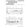
KRF-V5010/V6010/V7010/VR-205/206/207/255/257
CIRCUIT DESCRIPTION
FUNCTION DIODE MATRIX (X14-)
Model VR-205/255 VR-206/207 VR-209 VR-257 Function KRF-V5010 KRF-V6010/V7010 KRF-V8010 DOLBY DIGITAL X X X D503 SPEAKER A only D522 X X X TV & SAP X X D506 X
3. DESTINATION LIST OF TUNER
� TUNER
TUNER Destination type K1 1700 E1 E2 LW E3 RDS Q1 RDS BAND FM AM FM AM FM MW LW FM AM FM L FM H AM Receiving frequency range 87.5MHz~108.0MHz 530kHz~1700kHz 87.5MHz~108.0MHz 531kHz~1602kHz 87.5MHz~108.0MHz 531kHz~1602kHz 153kHz~279kHz 87.5MHz~108.0MHz 531kHz~1602kHz 65.0MHz~74.0MHz 87.5MHz~108.0MHz 531kHz~1602kHz Channel space 100kHz 10kHz 50kHz 9kHz 50kHz 9kHz 9kHz 50kHz 9kHz 10kHz 50kHz 9kHz IF +10.7MHz +450kHz +10.7MHz +450kHz +10.7MHz +450kHz +450kHz +10.7MHz +450kHz +10.7MHz +10.7MHz +450kHz PLL reference frequency 25kHz 10kHz 25kHz 9kHz 25kHz 9kHz 9kHz 25kHz 9kHz 5kHz 5kHz 9kHz Diode SW DSW3 DSW2 DSW1 DSW0 D507 D505 D504 D510 0 0 0 0 0 1 0 1 0 0 1 0
K, P, R Y, M, I, C, V, E, X, H T
E Q
0 1
1 0
0 1
1 1
0 : NONE DIODE, 1: ADD DIODE
3-1 Channel Space Selector in Broadcasting setting
1. Push the BAND key for 2 seconds in the standby mode. 2. Display shows "F100/A10kHz" or "F50/A9kHz" blinkingly for 5 seconds. 3. Turn the VOLUME knob (Encoder) to choose your channel space. 4. Push the BAND key to memorize the channel space to E2P ROM. Note : Channel space will be set by the data from E2P ROM if reconnect the power cord.. Channel space will be set by the destination data from E2P ROM if backup data damaged.
3 E2P ROM check (E, T, Q, M, V type) Check the reading data and the writing data of the E2P ROM after setting the test mode. Display shows blank if the reading and writing data is the same. Display shows "&" if the different. Data (FM 50kHz, AM 9kHz, De-emphasis 50us) will be written to E2P ROM if the unit for M and V type.
4-4 ACTIVE CONTENTS
1 The mute control is not activated when the mode is switched. 2 The test mode will be terminated by plugging it off the power source or by initializing it, when all the settings will be initialized. 3 During the test mode, it can be operated in a special manner that is different from an ordinary operation by using the keys on the remote control or the main body, specifically as shown in the following table (5. contents). 4 Channel space will be no change if set channel space in the reset mode.
4. TEST MODE
4-1 SETTING
Turn the power ON while pressing the [BAND] key.
4-2 CANCEL
Unplug the AC power cord from an AC power wall outlet.
4-3 STARTING ACTIVE CONTENTS
1 The power on state is entered whenever the power is turned on while pressing the [BAND] key. All functions are then initialized and activated in the all-lighting mode. 3 All lighting mode is canceled when any main unit's keys are pressed. The normal display obtained when the selector is set to TUNER then appears.
4-5 CONTENTS
TUNER (E, T, Q, RDS ONLY)
OPERATION KEY PTY DISPLAY BASS BOOST FUNCTION � S LEVEL � RF ATT FL DISPLAY Remarks (EXP.) (1) (1) (S LEVEL), (RF ATT) OFF (2) (S LEVEL), (RF ATT) ON (2) (3) (3) (NORMAL), (RF) ATT OFF CYCLIC
P. CALL UP P. CALL FREQUENCY P. CALL DOWN
9
|
|
|
> |
|