|
|
|
Who's Online
There currently are 5816 guests and
4 members online. |
|
Categories
|
|
Information
|
|
Featured Product
|
|
|
 |
|
|
There are currently no product reviews.
 ;
It's a good manual, this one it's a scan from the original factory service manual, great quality 100% readeable. definetely it worths what I paid for.
 ;
A good manual! fast service and good qualityi for pdf document.
thanks!
;
Very helpful and complete manual. Maybe only one negative is schematics have sometimes unreadable name of the parts. But it's not a big problem.
;
Excellent high quality schematics brought my old Heidelberg back to life. Fast download at a reasonable price. Thanks.
;
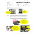
This document is just what I was looking for, it´s very useful, it contains adjustment procedures for the final stage of the power amp and also
has a complete wiring diagram and description of the main semiconductors used in the design.
KRC-31Y/36/366L/37/Y /391/394/Y/466R/4904Y
MICROCOMPUTER�S TERMINAL DESCRIPTION
q Microcomputer : UPD780058GCxxx (X14 : IC1)
Pin No. 1 2 3 4 5 6 7 8 9 10 11 12 13 14 15 16 17 18 19 20 21 22 23 24 25 26 27 Pin Name DSI PANEL AVSS L-RST L-CE AVREF1 PLL-DATA PLL-CLK L-DATA L L-DATA S L-CLK R-DATA R-QUAL CH-DATA C CH-DATA H CH-CLK M-STBY T-END ACC-DET BU-DET IC2 TYPE 0 IC2 TYPE 1 TYPE 0 TYPE 1 TYPE REF I/O O I O O I I/O O I O O I I I O I/O I �H� : Standby I I I I I I I O and service. 28 29 30 31 32 33 34 35 36 37 38 39 40 MOTOR PLL-CE SD ASF LO/DX VSS1 P-MUTE SVR IC2-SCL IC2-SDA MUTE P-STBY O O I �L� : Station does not exist O O O O O I/O O O Noise detection time constant switch. Local seeking switch. �H� : LO, �L� : DX GND. Power amplifier muting. SVR control. E-volume communication clock. E-volume communication data. Muting control. Power amplifier standby. 78 79 80 PHONE NOISE AV CONT I I O 76 77 S-METER T-MODE I I 73 74 75 XT1 VDD0 AVREF 0 I VDD. VDD. Reference voltage. SD detection. �H� : SD exists, �L� : SD does not exist Cassette tape mode detection. Navi mute : Over 2.5V, Tel mute : Less tha 2.5V Noise detection during FM mode. reference voltage. Cassette mechanism motor. �H� : ON, �L� : OFF Front-end communication ship enable. Station detection. �H� : Station exists, 68 69 70 71 72 VDD1 X2 X1 IC I VDD. Main system clock. Main system clock. Tape end detection. �H� : Run, �L� : Stop ACC detection. Backup detection. For service. �L� : Normally For service. �L� : Normally Destination discrimination. Destination discrimination. Reference voltage for destination 59 60 61 62 63 64 65 66 67 SUBRESET REMOTE R-CLK CH-REQ C PACK-IN KEY-REQ VSS0 O I I I I I I Sub motor control. System reset. Remote control. RDS clock. Changer request. Cassette tape pack-in detection. Key signal detection. GND. Function / Operating Condition DSI control. Panel detection. �L� : Panel exists GND. LCD driver reset. LCD driver chip enable. Reference voltage. Front-end communication data. Front-end communication clock. LCD driver communication data. LCD driver communication data. LCD driver communication clock. RDS data. 55 RDS QUAL. Changer communication data. Changer communication data. Changer communication clock. Cassette tape standby detection. 57 58 FWD/REV SUB+ I O 56 EQ-MUTE O MS-CONT O �H� : Play, �L� : FF/REW Cassette tape muting. �H� : ON, �L� : OFF Cassette tape runing direction detection. �H� : FWD, �L� : REV Sub motor control. 54 MUSIC I Pin No. 41 42 43 44 45~47 48 49 50 51 52 53 Pin Name P. CON-DET CH-CONT CH-REC H EN2-1 EN2-0 BEEP EN3 EN1 SW 5V I/O I O O O O O O O O Function / Operating Condition P. CON short-circuited detection. Changer control. Changer request. Power supply IC control. Power supply IC control. Buzzer. Power supply IC control. Power supply IC control. P. ON 5V control. �H� : OFF, �L� : ON Tape signal detection. �H� : Signal does not exist, �L� : Signal exists tape advanced sensitivity control.
4
|
|
|
> |
|