|
|
|
Who's Online
There currently are 5911 guests online. |
|
Categories
|
|
Information
|
|
Featured Product
|
|
|
 |
|
|
There are currently no product reviews.
 ;
I received the manual in correct time. It was a perfect help for me.
;
excellent quality, contains circuits and scan quality, 226 pages
 ;
Great price for the manual and easy to locate on the site and download. I would buy again.
;
Very good copy of Manual, clear and easy to print off, arrived very promptly and reasonably priced. Thanks, I will use you again
;
The service manual when downloaded and printed out was clear and easy to read. The manual is complete with the schematic diagram and technical data. I occasionally require a manual and now having registered with this company I shall order from them in the future.
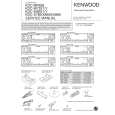
Removing the Unit
Removing the hard rubber frame 1 Engage the catch pins on the removal tool and
remove the two locks on the upper level. Upper the frame and pull it forward as shown in the figure.
Removing the Unit 1 Refer to the section <Removing the hard rubber 2 3
frame> (page 44) and then remove the hard rubber frame. Remove the screw (M4 � 8) on the back panel. Insert the two removal tools deeply into the slots on each side, as shown.
Screw (M4X8) (commercially available)
Lock Catch
Accessory2 Removal tool
2 When the upper level is removed, remove the
lower two locations.
Accessory2 Removal tool
4 Lower the removal tool toward the bottom, and
pull out the unit halfway while pressing towards the inside.
� The frame can be removed from the bottom side in the same manner.
� Be careful to avoid injury from the catch pins on the removal tool.
5 Pull the unit all the way out with your hands,
being careful not to drop it.
44 |
English
|
|
|
> |
|