|
|
|
Who's Online
There currently are 5360 guests online. |
|
Categories
|
|
Information
|
|
Featured Product
|
|
|
 |
|
|
There are currently no product reviews.
 ;
Good price, very legible manual, exactly what I needed -- but had to wait a day to actually get the download of the manual. Would have preferred to download it immediately after payment rather than waiting for someone to "process" my order. I was surprised that I had to wait that long.
;
As the only source for this manual it rather rank quite high since it is well scanned and perfectly readable.
 ;
the manual is in good quality and it's in pdf. manual was send in less then 24h.
regards
mike
;
I would not plug this machine in without finding a manual like this. In addition to setup and normal operating instructions, it has troubleshooting flowcharts, diagrammed mechanical adjustments, and schematics to beat the band. The tech I hand it to would be thrilled to find solder side PCB diagrams with component outlines superimposed, pinouts for every IC chip, and line drawings of transistors, with labeled legs.
As for printing quality, this may be a copy of a copy, but even the finest print when enlarged is very legible. There is a bit of grayed print over a few pages, as if a wet page were placed over it, but the print is still very legible. If you could borrow an original manual and get it printed and bound for 4 to 6 times the cost, you could get better quality. In that case you wouldn't be here. For price, utility, and availability I am rating this manual highly.
;
I received the Manual in a timely manner and it was exactly what I needed.
This is a perfect copy of the Service Manual, The quality is great. I am very
happy. Thank you
KDC-V7521/Y
CIRCUIT DESCRIPTION/ATTENTION
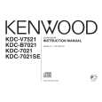
Variable Illumination Circuit
Using a DAC that can be varied in 256 steps between 0V and 5V and varying DAC output voltage, the currents that flow among R7, R9 and R11 are controlled. As a result, the brightness of red, blue and green is adjusted. to the buffer and that will be the input voltage of the V-I converter in the next stage with the voltage waveform of C . The V-I converter has the function of supplying electric current in proportion to the voltage input. For example, let us assume that the current flowing in the red LED is IR, and IR = (Q4 base voltage-VBE) /R7. From this, IR flows in proportion to Q4 base voltage. Therefore, V-I converter will supply current in proportion to the voltage input to red, blue and green LED's, which vary the brightness of LED's. The registor between D1 and V-I converter is the protection registor for limiting power supplied to transistors (Q4-6).
Description of Operation The voltage output from DAC will be in the step-wise waveform as shown in A . When the output voltage is put through R1-3 and C1-3 lowpass filters for removing noise and smoothing voltage waveforms, we get the voltage waveform of B . The voltage that went through the low-pass filters is input
4.7
ILL+B D1 PAN5V DAC
R4 100k
R LOW PASS FILTER 1 2 3 4 R1 R2 R3 100k 100k 100k
R5 100k
G
B
IC1
8 SDA SCL 7 6 VCC SDA AO1 AO2 AO3 NC
Q2
R6 100k
Q1
V
BUFFER
PROTECTION RESISTOR
Q3 Q4
V
(R) (G) (B)
C2 C3 4.7
5 SCA GND
V-I CONVERTER
Q5 Q6
(BOTTOM VIEW)
C1 4.7
A GND
B
R7 270 R8 220
C
A : DAC OUT
B : BUFFER INPUT
C : V-I CONVERTER INPUT
R9 470 R10 150 R11 470 R12 150
V
T
T
T
ATTENTION Assembly pf FPC (Flexible PC board) onto Roller ass�y Turn Roller ass�y by 2 times. Hook the end of Roller ass�y to the tongue. Insert the FPC into the slit of Roller ass�y then release the end of Roller ass�y and the tongue.
FPC tongue
Turn 2 times.
End of Roller ass�y
10
|
|
|
> |
|