|
|
|
Who's Online
There currently are 6043 guests online. |
|
Categories
|
|
Information
|
|
Featured Product
|
|
|
 |
|
|
There are currently no product reviews.
 ;
Complete manual as pdf-file in very good quality. Very helpful and fast availability.
 ;
Complete service manual in very good scanning quality with all schematic and PWB graphics as well as assembly & maintenance instructions. A slight drawback is that the rastering of the PWB graphics sometimes makes it a bit difficult to follow fine traces, but no showstopper.
;
Purchased the manual that I was looking for at a great price and could download it easily.. Great service experience and for future purchases I plan to use the site. Thank you very much
;
Service manual in good quality, it was very helpful to me. Perfect service, I am very satisfied.
Jochen Kelm
;
Exellent manual ,it was in great condition,and got all the info i expected,5 stars!!
KDC-CX89/CMP59FM/C719MP/CPS89MP
ADJUSTMENT
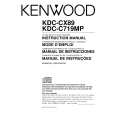
L.P.S initial position adjustment procedure
1. Connect the changer to the H/U. 2. While holding the magazine eject button of the changer, press the reset button of the H/U. 3. After about 3 seconds, release the magazine eject button. 4. Press the SRC button of the H/U to enter the CD-CH mode, and the H/U's display section indicates "E-88". 5. Move the mechanism deck to around the 1st stage by pressing the DISC- or DISC+ button. 6. Insert the adjustment tool (W02-0635-00) into the tool hole on the changer mechanism. 7. Then press the DISC+ button to move the mechanism deck until the mechanism's slider hits the adjustment tool. 8. When the motor locks (stops), press the REPEAT key of the H/U. When the REPEAT key is pressed, the mechanism moves automatically to the 1st stage and the initial position adjustment completes. (The data is written in the EEPROM at this time.)
W05-0635-00
For KDC-CMP59FM
RF MODULATOR UNIT
1. DC balance adjustment (VR301) While observing the waveform with an oscilloscope at pin 13 of IC301, adjust VR301 to minimize the waveform level. 2. PLL control voltage adjustment (VC301) First set the transmission frequency to �87.9MHz with the commander, then adjust VC301 so that the DC Voltage at the +pole of C317, measured using a multi-meter or digital tester, is +3V (±0.1V). �NOTE: E type is 87.7MHz. 3. Modulation level adjustment (VR303) The method uses a standard receiver or tuner. Adjust VR303 so that the output level from the standard receiver or tuner is as specified.
9
|
|
|
> |
|