|
|
|
Who's Online
There currently are 6021 guests online. |
|
Categories
|
|
Information
|
|
Featured Product
|
|
|
 |
|
|
There are currently no product reviews.
 ;
Exactly what was needed to assess the product - excellent value and great service
 ;
Nice to have the service manual for the Sony DCR-TRV345E now. The document is of excellent quality.
;
MACKIE HR824 26 pages English-only Service Manual contains:
1) HR824 technical overview with the description of front and rear panel switches.
2) HR824 specs
3) Block Diagram
4) Wiring Diagram
5) Packaging management
6) Spare part & final assembly list (for PCB rev A and B) + exploded view
7) Test Procedures (where, how to measure voltage...) including Test Point diagram on the PCB.
8) IC and Transistor charts.
Excellent guide: very clear, good scan quality enabling us to print readable diagram :-)
Note:
Mackie HR824 make extensive use of surface mount devices (SMD). Service on the HR824 must
only be undertaken by experienced service technicians with the right tools, experience and patience to perform surface mount rework when needed.
;
This Service manual is very well scanned and its clean to read, no any anti-theft words that un-english could understand. I got my CCD600 working with this manual and it´s clear shematics :)
;
I was very pleased with the service provided and was surprised at how good the quality was of the manual. I thought it may be a third generation copy or so, but it is as good as the websites that charge 3 times this much. I repair some electronics for family and friends without charge, so this is perfect for me. Thank you very much.
KDC-3023R,4024/V/Y/YV
ADJUSTMENT
1. IC10 (TDA7513) -The Tuner adjustment method
� When IC10 and its circumference are fixed, according to the following order, it readjusts if needed. � The adjustment item changes with parts to exchange. Please refer to "Parts vs Adjustment item table". 1-1. VCO Coil Adjustment -- Adjustment of Tunning Voltage Voltage Check Point : Vt-Check Land (PWB Side_B, around D506) Adjustment Coil : L507 (VCO Coil) The adjustment method : VCO coil is turned and adjusted according to the following tables.
TYPE E/M K J W(Wide Band) Mode AM AM FM FM freq. 1611kHz 1700kHz 90.0MHz 108.0MHz Voltage 5.5 ± 0.1(V) 5.8 ± 0.1(V) 5.6 ± 0.1(V) 7.2 ± 0.1(V) Fig (C) (C) (C) (C)
1-3. Adjustment of FM_ANT&RF Coil Voltage Check Point : S_METER-Check Land (PWB Side_B, around W572) Adjustment Coil : ANT_Coil = L505 RF_Coil = L506 Setting of Signal Generator : Refer to the following tables.
TYPE E/M K J W(Wide Band) MODE FM FM FM FM freq. 87.5MHz 87.9MHz 76.0MHz 65.0MHz Mod. OFF OFF OFF OFF ANT Input 5 or 11dBuEMF 5 or 11dBuEMF 5 or 11dBuEMF 5 or 11dBuEMF Fig (A),(C) (A),(C) (A),(C) (A),(C)
xThe appearance and the coil with which S-METER DC voltage serves as the maximum are turned and adjusted in the above-mentioned SG input. �By the above-mentioned adjustment method, same adjustment is performed to both sides (ANT&RF Coil). 1-4. Adjustment of STEREO (adjustment of 456k-VCO) Adjust in TEST_MODE � How to enter the test mode While pressing on [ FM ] and [ PRESET 6 ] keys, reset the unit. � Adjustment method Complete on condition that show "ALL OFF" when pressing on [ PRESET 1 ] and [ PRESET 6 ] keys. (Writing adjustment valve to the EEPROM.) Effect of adjustment is in cofirmation of adjustment status at [ PRESET 4 ] key. � Display of [ PRESET 4 ] Adjustment "OK" : 14seg model "E2P OK" 7seg model "EPO" Adjustment "NG" : 14seg model "E2P ERR" 7seg model "EPE" � Releasing the test mode Reset mode only. ACC off, Power off, Power down and Remove the panel mode is not releasing.
M : AM Adjustment For Your Information : The frequency of SET is only set up by Pre-Set-Key in case this adjustment 1-2. Adjustment of 1st & 2nd-MIX Coil Voltage Check Point : S_METER-Check Land (PWB Side_B, around W572) Adjustment Coil : 1stIFT = L508 / 2ndIFT = L509 Setting of Signal Generator : Refer to the following tables
TYPE K E,M,J,W MODE AM AM freq. 1000kHz 999kHz Mod. OFF OFF ANT Input 35dBuEMF 35dBuEMF Fig (B),(C) (B),(C)
xThe appearance and the coil with which S-METER DC voltage serves as the maximum are turned and adjusted in the above-mentioned SG input. �By the above-mentioned adjustment method, same adjustment is performed to both sides (1st&2nd MIX Coil).
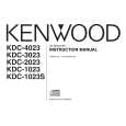
(REAR VIEW)
(TUNER ANT)
[Fig.1]
FM-SG AM-SG
(A) (B)
L505 L506 L507 L508
(C) DC Voltmeter Vt Check Land IC10
L509
S-METER Check Land (OVER VIEW) (UNDER VIEW)
[Fig.2]
[Fig.3]
8
|
|
|
> |
|