|
|
|
Who's Online
There currently are 5928 guests online. |
|
Categories
|
|
Information
|
|
Featured Product
|
|
|
 |
|
|
There are currently no product reviews.
 ;
Quick site processing. A complete and very useful manual with all details. Thank you!
;
Quick service response. A useful and very rare service manual with all details. I recomend this service.
;
I ordered this manual sometime in the afternoon and I received it on my e-mail the same evening.
This is a fantastically good and properly scanned copy of the original manual. All pages are of the same scale and they overlap each other. It means that you can print the manual and easily make it as a convenient paper manual.
The content of the manual is fantastic. Alignment descriptions, PCB layouts and elementary diagrams are explicit and precise. I immediately found what I was looking for. Thanks to this manual and Owner-Manuals.com my amplifier is alive again. Many thanx indded!
;
The manual was well-scanned and easy to read. As an added bonus, the Operator's Manual was bundled with the Service Manual!
I'd definitely use owner-manuals.com again.
;
Finally, i found one website, where i can download this service manual , and fix my hifi. The service manual is very good, and easy to download and to print.
DP-SG7/SG7G
ADJUSTMENT
No. ITEM INPUT SETTINGS OUTPUT SETTINGS PLAYER SETTINGS ALIGNMENT POINTS ALIGN FOR FIG.
While pressing the "REPEAT" key, turn the AC ON. { Refer to test mode (MODE 0 0) } On the power from 0.08 to 0.15 mW, when the diffraction grating is correctly aligned with the RF level of 0.6 Vp-p or more.
1
LASER POWER
�
Apply the sensor section of optical power meter on the pickup lens.
Press the PLAY/PAUSE key, then confirm that the LED is "03".
�
(a)
2
FOCUS ERROR BIAS
Test disc Type 4
Connect an oscilloscope as follows. CH1 : RF (CN3 pin 1) CH2 : TE (CN3 pin 6)
Press the PLAY/PAUSE key, then confirm that the LED is "05".
FE BIAS VR2
Optimum eye pattern
3
TRACKING ERROR BALANCE
Test disc Type 4
Connect an oscilloscope as follows. CH1 : RF (CN3 pin 1) CH2 : TE (CN3 pin 6)
Press the PLAY/PAUSE key, then confirm that the LED is "03".
TE BALANCE VR1
Symmetry between upper and lower patterns
4
TRACKING GAIN
Test disc Type 4 Connect a LPF to CN3 Apply signal of pin 5-6 to which you 1.2 kHz, connect an oscilloscope 50mVrms to or AC voltmeters. CN3 pin 5-6.
Press the PLAY/PAUSE key, then confirm that the LED is "05".
TRACKING GAIN VR3
Two VTVMs should read the same value.
(e)
Note: Type 4 disc : SONY YEDS-18 Test Disc or equivalent.(KTD-0V) LPF: Around 47 k�+ 390 pF or so. Step 1~4 are in Test Mode.
(a) Laser power
0.08 0.15 mW
(e) Tracking gain
CN3
1 2 3 RF FE1 FE2 VC TE2 TE1
VC L.P.F. L.P.F. + + VTVM VTVM
_
1.2 kHz 50 mVrms
4 5 6
+
Pickup
Optical power meter
7 S.S
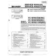
ALIGNMENT POINTS
CN1
T-GAIN
TE-B
FE-B
VR3
VR1
VR2
4
|
|
|
> |
|