|
|
|
Who's Online
There currently are 5869 guests online. |
|
Categories
|
|
Information
|
|
Featured Product
|
|
|
 |
|
|
There are currently no product reviews.
 ;
This is a high quality manual with clear schematic and components layout diagrams ; with service procedure included.
 ;
This service manual for the Kenwood KT-990D was reproduced really well ,is very legible and manual is complete.Combined with the low price paid,in the future,I will be checking Owner-Manuals.com any time I need a manual.
;
When I purchased this manual I had my doubts regarding the quality as the price was so reasonable as compared to other outlets.
The manual itself is of high standard the print is very clear as are the diagrams. Obviously with the diagrams one has to zoom in otherwise it is to small to be able to read.
Overall I am very pleased with the company who delivered as they said and with the manual they supplied.
I occasionally require a manual and now having registered with this company I shall order from them in the future.
;
I was at first dubious about payiong for downloaded manuals but having done so, I was extremely impressed with quality of the two manual I ordered, well worth the small price I paid.
I would highly recommend these to my friends.
;
reasonable price for the schematic - the service is perfect, all as expected and pointed by instructions - good scan of the original plans - thank you!
K
L
M
N
O
2/3 3.3V AVR
1
CN102
SENSE MNT1(SHCK) DQSY DIG-RST SQSY SCL XINT MNT2(XBUSY) LDON GND MOD REC SW REFLECT PHOTO SW PROTECT NC (EMPH) STTLMT DISC IN +5V
A
X25CN3
2SA954 2SC2003
UN5212
2SD2012
IC10
1.1V
A A A
2 3 4 5 6
C190
C195 1
5.1V
7 8 + 9 10
100u
(MDM-04)
SLT SW CN1
(X29-2580-00) (A/2)
3.3V 5 A
6.3 +
W3 4
W2 3
C187
W4
11 2 12
1 2
+5V A
5V 1
13 14 100u 6.3 15 16 17 18 19
LOAD MOTOR M
(X29- ) (B/2)
SLED MOTOR M CN2 SPINDLE MOTOR M
+5V 2 3 2 1 3 2 1
PROTECT S1
WH1 REC SW S2
+5V
PH1
3
1 R2
4
CN105
1 2 3 4 5 6 7 8 9 10 11 12 13 14 15 PHOTO SW REC SW SPDLSPDL+ NC +5V DISC IN SLEDSLED+ REFRECT PROTECT GND STTLMT LOAD-OUT LOAD-IN
180
15
14
13
12
11 NC
10 +5V
9
8
7
6 REFRECT
5 PROTECT
4
3
2
1
CN3
PHOTO SW
PH1 : T95-0140-05
2SA1048 2SC2458
IC1 IC2 IC3 IC4 IC5 IC6 IC7 IC8 IC10 IC11 Q1 Q2,3 Q4,5 Q6 Q7 Q8 Q9 Q10 : CXA2523AR : CXD2652AR : TC7S08FU : TC7WU04FU : TC74ACT540FS : X24C01AS-2.7 : HM51W4400BTT-7 : BH6511FS : L88MS33T : AK4520 : FMW1 : DTA144EUA : DTC114YUA : 2SA1576A(R,S) : 2SB798-DL : 2SJ278 : 2SK1764 : DTC114EUA
R1
KAN03
4.7K REC SW SPDL-
CN101
1 2 3 SCLK SRDT XLATCH
4 5 6 7 8 9
R120
WRPWP SWDT MNT3(SLOCK) MNT0(FOK) SDA SCTX ADDT MGND BCK MGND
D1,2 : F1J6TP D101 : MA101
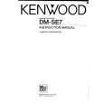
CAUTION: For continued safety, replace safety critical components only with manufacturer's recommended parts (refer to parts list). indicates safety critical components. For continued protection against risk of fire, replace only with same type and rating fuse(s). To reduce the risk of electric shock, leakage-current or resistance measurements shall be carried out (exposed parts are acceptably insulated from the supply circuit) before the appliance is returned to the customer.
DISC IN SLEDSLED+ GND STTLMT LOAD OUT LOAD IN
10
100
11 12 13
R124
2/3
14 DADT M+5V LRCK M+5V LOAD-IN GND LOAD-OUT GND 3.3V DIN H+5V DOUT +5V +5V 512FS HGND +B -B
The DC voltage is an actual reading measured with a high impedance type voltmeter. The measurement value may vary depending on the measuring instruments used or on the product. Refer to the voltage durX25CN2
100
15 16 M+5V 17 18 19 20 21 +3.3V 22 23 H+5V 24 25 +5V C196 28 0.1 29 26 27
B
ing RECORDABLE MD PLAY unless otherwise specified; The value shown in ( ) is the voltage measured at the moment of STOP. The voltage followed by (REC) refers to the value during MD RECORDING.
NON () <> X
STOP PLAYBACK RECORD MEASUREMENT IMPOSSIBLE
PLAYBACK PLAYBACK(DIGITAL OUTPUT) RECORD RECORD(DIGITAL INPUT) GND LINE +B LINE -B LINE
SPDL+
DM-SE7/SE7(G)/SE9(K) (1/3)
H+5V
DM-SE7/SE7(G)/SE9
Y22-7210-00
|
|
|
> |
|