|
|
|
Who's Online
There currently are 6013 guests online. |
|
Categories
|
|
Information
|
|
Featured Product
|
|
|
 |
|
|
There are currently no product reviews.
 ;
as always, rapid and efficient, very good and clear prints
details clearly visible keep going this way!!!!!!
;
I expect a wonderful result as alaways!!!!!!
Usually is much faster....
;
Wow very wonderful and clear!!!! I will always trust them
;
Providing the manual works fine, quickly and without any problems for an acceptable price. After printing the service manual it took me only a short time to repair my carradio from Clarion. Thank You! Greetings from Heiko
;
I was searching a way to modify the original phono-in entry (for connection of vynil disc player, with RIAA equalization) to a line-in entry (for connection of modern analog entries, eg. ipod, mp3player).
This service manual gave me the correct hints.
It contains very useful infos for repairing and modifing the hi-fi, such as disassembling instructions, block diagrams, schematic diagrams, PCB prints, replacement parts list.
Very good!
103SW/SW-301/1050SW/SW-501
CONTENTS/DISASSEMBLY FOR REPAIR/ADJUSTMENT
Contents
SPECIFICATIONS ........................................Top cover CONTENTS ............................................................... 2 DISASSEMBLY FOR REPAIR....................................2 ADJUSTMENT ............................................................2 PC BOARD ................................................................ 3 SCHEMATIC DIAGRAM ............................................ 5 EXPLODED VIEW ......................................................7 PARTS LIST................................................................8
DISASSEMBLY FOR REPAIR
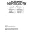
< How to remove the front panel >
1. Remove the decoration plate (1) by a pincette to the bottom of the front panel, then remove the 3 screws (2). 2. 103SW/SW-301: Remove the front panel in the upper slanting direction of the arrow (3). 1050SW/SW-501 : Remove the front panel just the frontwards.
2 x3
3
1
1
ADJUSTMENT
No. ITEM INPUT SETTINGS OUTPUT SETTINGS AMPLIFIER SETTINGS ALIGNMENT POINTS ALIGN FOR FIG.
Unless otherwise specified, the individual switches should be set as following : POWER : ON NO SIGNAL INPUT 1 IDLE CURRENT � Connect a DC voltmeter to R611
(a)
VOLUME : 0
VR601
5 mV
(a)
Dc voltmeter
5 mV
R611
2
|
|
|
> |
|